RB Robotics
|
|
|
RB Robotics |
|
|
||
|
|
Updated 4-7-2007 CPU Board Assembly Approximate Build Time: 2-3 hours Parts List
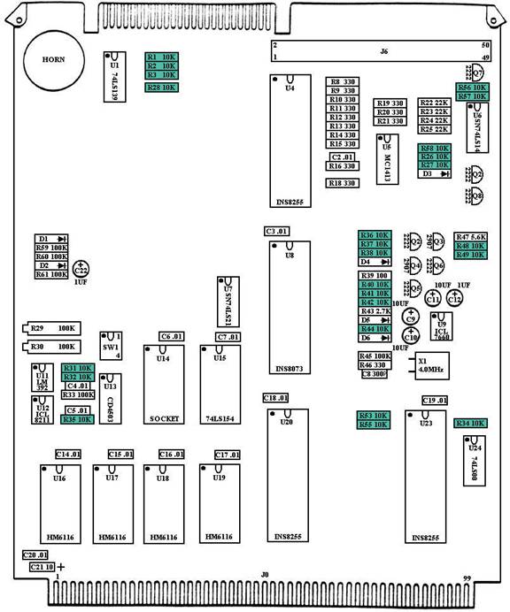
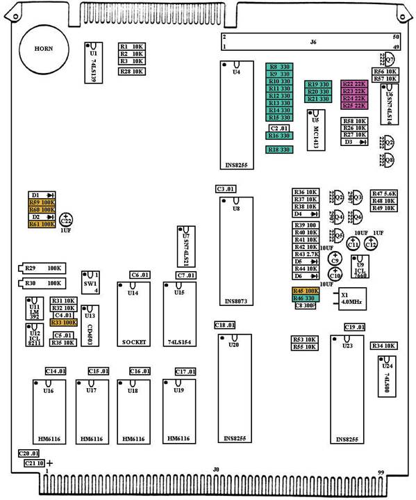
Assembly Steps:Refer to CPU Diagram 1 ( ) Install R1: 10K Ohm resistor (Brown-Black-Orange-Gold) ( ) Install R2: 10K Ohm resistor (Brown-Black-Orange-Gold) ( ) Install R3: 10K Ohm resistor (Brown-Black-Orange-Gold) ( ) Install R26: 10K Ohm resistor (Brown-Black-Orange-Gold) ( ) Install R27: 10K Ohm resistor (Brown-Black-Orange-Gold) ( ) Install R28: 10K Ohm resistor (Brown-Black-Orange-Gold) ( ) Install R31: 10K Ohm resistor (Brown-Black-Orange-Gold) ( ) Install R32: 10K Ohm resistor (Brown-Black-Orange-Gold) ( ) Install R34: 10K Ohm resistor (Brown-Black-Orange-Gold) ( ) Install R35 - 10K Ohm resistor (Brown-Black-Orange-Gold) ( ) Install R36 - 10K Ohm resistor (Brown-Black-Orange-Gold) ( ) Install R37 - 10K Ohm resistor (Brown-Black-Orange-Gold) ( ) Install R38 - 10K Ohm resistor (Brown-Black-Orange-Gold) ( ) Install R40 - 10K Ohm resistor (Brown-Black-Orange-Gold) ( ) Install R41 - 10K Ohm resistor (Brown, Black, Orange,Gold) ( ) Install R42 - 10K Ohm resistor (Brown, Black, Orange,Gold) ( ) Install R44: 10K Ohm resistor (Brown-Black-Orange-Gold) ( ) Install R48 - 10K Ohm resistor (Brown-Black-Orange-Gold) ( ) Install R49 - 10K Ohm resistor (Brown-Black-Orange-Gold) ( ) Install R53 - 10K Ohm resistor (Brown-Black-Orange-Gold) ( ) Install R55 - 10K Ohm resistor (Brown-Black-Orange-Gold) ( ) Install R56 - 10K Ohm resistor (Brown-Black-Orange-Gold) ( ) Install R57 - 10K Ohm resistor (Brown-Black-Orange-Gold) ( ) Install R58 - 10K Ohm resistor (Brown-Black-Orange-Gold)
CPU Diagram 1
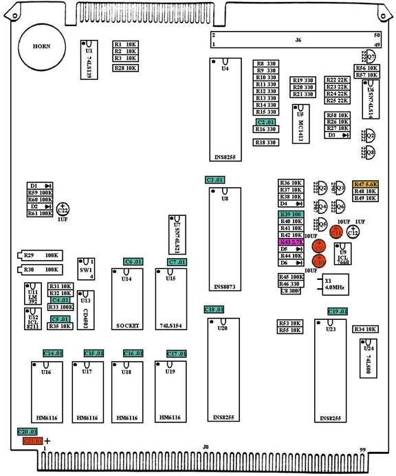
Refer to CPU Diagram 2 ( ) Install R8 - 330 Ohm resistor (Orange-Orange-Brown-Gold) ( ) Install R9 - 330 Ohm resistor (Orange-Orange-Brown-Gold) ( ) Install R10 - 330 Ohm resistor (Orange-Orange-Brown-Gold) ( ) Install R11 - 330 Ohm resistor (Orange-Orange-Brown-Gold) ( ) Install R12 - 330 Ohm resistor (Orange-Orange-Brown-Gold) ( ) Install R13 - 330 Ohm resistor (Orange-Orange-Brown-Gold) ( ) Install R14 - 330 Ohm resistor (Orange-Orange-Brown-Gold) ( ) Install R15 - 330 Ohm resistor (Orange-Orange-Brown-Gold) ( ) Install R16 - 330 Ohm resistor (Orange-Orange-Brown-Gold) ( ) Install R18 - 330 Ohm resistor (Orange-Orange-Brown-Gold) ( ) Install R19 - 330 Ohm resistor (Orange-Orange-Brown-Gold) ( ) Install R20 - 330 Ohm resistor (Orange-Orange-Brown-Gold) ( ) Install R21 - 330 Ohm resistor (Orange-Orange-Brown-Gold) ( ) Install R46 - 330 Ohm resistor (Orange-Orange-Brown-Gold) ( ) Install R22 - 22K Ohm resistor (Red-Red-Orange-Gold) ( ) Install R23 - 22K Ohm resistor (Red-Red-Orange-Gold) ( ) Install R24 - 22K Ohm resistor (Red-Red-Orange-Gold) ( ) Install R25 - 22K Ohm resistor (Red-Red-Orange-Gold) ( ) Install R33 - 100K Ohm resistor (Brown-Black-Yellow-Gold) ( ) Install R45 - 100K Ohm resistor (Brown-Black-Yellow-Gold) ( ) Install R59 - 100K Ohm resistor (Brown-Black-Yellow-Gold) ( ) Install R60 - 100K Ohm resistor (Brown-Black-Yellow-Gold) ( ) Install R61 - 100K Ohm resistor (Brown-Black-Yellow-Gold)
CPU Diagram 2
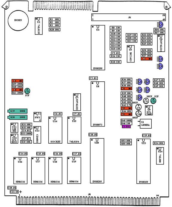
Refer to CPU Diagram 3 ( ) Install R39 - 100 Ohm resistor (Brown-Black-Brown-Gold) ( ) Install R43 - 2.7K Ohm resistor (Red-Purple-Red-Gold) ( ) Install R47 - 5.6K Ohm resistor (Green-Blue-Red-Gold) ( ) Install C2 - .01uF ceramic capacitor (marked 103) ( ) Install C3 - .01uF ceramic capacitor (marked 103) ( ) Install C4 - .01uF ceramic capacitor (marked 103) ( ) Install C5 - .01uF ceramic capacitor (marked 103) ( ) Install C6 - .01uF ceramic capacitor (marked 103) ( ) Install C7 - .01uF ceramic capacitor (marked 103) ( ) Install C14 - .01uF ceramic capacitor (marked 103) ( ) Install C15 - .01uF ceramic capacitor (marked 103) ( ) Install C16 - .01uF ceramic capacitor (marked 103) ( ) Install C17 - .01uF ceramic capacitor (marked 103) ( ) Install C18 - .01uF ceramic capacitor (marked 103) ( ) Install C19 - .01uF ceramic capacitor (marked 103) ( ) Install C20 - .01uF ceramic capacitor (marked 103) ( ) Install C9 - 10 UF electrolytic capacitor. The positive end must face the top edge of the board (the end with the smaller edge connector). ( ) Install C10 - 10 UF electrolytic capacitor. The positive end must face the top edge of the board (the end with the smaller edge connector). ( ) Install C11 - 10 UF electrolytic capacitor. The positive end must face the top edge of the board (the end with the smaller edge connector). ( ) Install C21 - 10 UF electrolytic capacitor. The positive end faces right (toward the middle of the board.)
CPU Diagram 3
Refer to CPU Diagram 4 ( ) Install C12 - 1 UF electrolytic capacitor. The positive end must face the top edge of the board (the end with the smaller edge connector) ( ) Install C22 - 1 UF electrolytic capacitor. The positive end must face the top edge of the board (the end with the smaller edge connector). ( ) Install C8 - 300PF (marked 301K) capacitor. ( ) Install D1 - IN4148 Diode. Make sure the end with the band faces right (orientation is marked on the board for each diode.) ( ) Install D2 - IN4148 Diode. Make sure the end with the band faces right (orientation is marked on the board for each diode.) ( ) Install D3 - IN4148 Diode. Make sure the end with the band faces right (orientation is marked on the board for each diode.) ( ) Install D4 - IN4148 Diode. Make sure the end with the band faces right (orientation is marked on the board for each diode.) ( ) Install D5 - IN4148 Diode. Make sure the end with the band faces right (orientation is marked on the board for each diode.) ( ) Install D6. - IN4148 Diode. Make sure the end with the band faces right (orientation is marked on the board for each diode.) ( ) Install Q1 - PN2222 Transistor ( ) Install Q2 - PN2222 Transistor ( ) Install Q5 - PN2222 Transistor ( ) Install Q6 - PN2222 Transistor ( ) Install Q7 - PN2222 Transistor ( ) Install Q8 - PN2222 Transistor ( ) Install Q3 - PN2907 Transistor ( ) Install Q4 - PN2907 Transistor ( ) Install R29 - 100K Potentiometer. The screw on the potentiometer faces to the left or outside of the board. ( ) Install R30 - 100K Potentiometer. The screw on the potentiometer faces to the left or outside of the board.
CPU Diagram 4
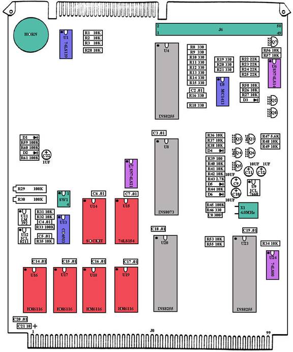
Refer to CPU Diagram 5 ( ) Install X1 - 4MHz Crystal. Ensure it lays flat on the board before soldering. ( ) Insert the 4-position DIP Switch in SW1. The notch faces the top of the board. ( ) Install J6 - 50 pin locking header. The key faces the bottom of the board. ( ) Install the Horn into position H1. The positive side faces left. ( ) Insert 8-position DIP Socket at U9 ( ) Insert 8-position DIP Socket at U11 ( ) Insert 8-position DIP Socket at U12 ( ) Insert 14-position DIP Socket at U6 ( ) Insert 14-position DIP Socket at U7 ( ) Insert 14-position DIP Socket at U24 ( ) Insert 16-position DIP Socket at U1 ( ) Insert 16-position DIP Socket at U5 ( ) Insert 16-position DIP Socket at U13 ( ) Insert 24-position DIP Socket at U14 ( ) Insert 24-position DIP Socket at U15 ( ) Insert 24-position DIP Socket at U16 ( ) Insert 24-position DIP Socket at U17 ( ) Insert 24-position DIP Socket at U18 ( ) Insert 24-position DIP Socket at U19 ( ) Insert 40-position DIP Socket at U4 ( ) Insert 40-position DIP Socket at U8 ( ) Insert 40-position DIP Socket at U20 ( ) Insert 40-position DIP Socket at U23
CPU Diagram 5
( ) Using antistatic devices, insert the following IC chips into the correct positions (notch faces towards top of board): ( ) U1 is Decoder SN74LS139. ( ) U5 is Driver MC1413. ( ) U6 is Inverter SN74LS14. ( ) U7 is Dual AND SN74LS21. ( ) U9 is Voltage Inverter ICL7660. ( ) U11 is Comparator LM392. ( ) U12 is Voltage Sensor ICL8211. ( ) U13 is Hex Buffer CD4503. ( ) U15 is Decoder 74LS154. ( ) U16, U17, U18, and U19 are Memory 2Kx8 HM6116. ( ) U24 is Quad NAND 74LS00 ( ) U4, U20, and U23 are Programmable I/O INS8255. ( ) U8 is the Microprocessor INS8703. ( ) Install the two board tabs. Use a pair of pliers to squeeze the retaining bars in. This concludes your CPU Board assembly. Set it aside until called for later.
|
|
|||||||||||||||||||||||||||||||||||||||||||||||||||||||||||||||||||||||||||||||||||||||||||||||||||||||||||||||||||||||||||||||||||||||||||||||||||||||||||||||||||||||||||||||||||||||||||||||||||||||||||||||||||||||||||||||||||||||||||||||||||||||||||||||||||||||||||||||||||||||||||
|
Copyright © 2005 RB Robotics | |