RB Robotics  

Email: rb5x@rbrobotics.com

Products | Specs | Curriculum | Parts Dept | Service Dept | Downloads | Forums | Support | Links | History | FAQs | Owners Mods | For Builders

Home
Motor Control Board
Adjustments
Base Assembly
Skirt Assembly
Switch Ring Assm
Switch Harness
Chassis Assembly
EPROM Board
Interface Board
Shutdown Board
Interface Panel
New Sonar Interface
Back Plane
Card Cage
CPU Board
LED Board
Voice / Sound Board
Final Assembly
Charger

Chassis Assembly

Approximate Build Time:

Parts List

2000-35005


2

Cable, Battery

3001-03002


1

Transducer Bracket

2001-03008


2

Battery Support

3001-03005


2

Battery Hold Down 

2000-76001


1

Battery 10 AH

2000-76000


1

Battery 5AH

2000-35005


2

Cable, Battery

3001-03002


1

Transducer Bracket

2001-03008


2

Battery Support

3001-03005


2

Battery Hold Down

2000-76001


1

Battery 10 AH

2000-76000


1

Battery 5 AH


Assembly Steps:


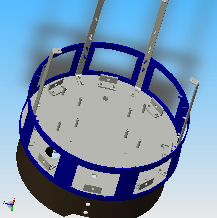
Place the Switch Ring on the Base Plate. The two Chassis Frame Supports that are closest to each other should be opposite the charge pins (the holes in the lower skirt.) Secure using Keps Nuts.

Mount the Sonar Transceiver Bracket on the Chassis Frame Supports (the large hole should be directly above the charge pin holes in the lower skirt.) Orient the bracket so that the rectangular cutout in the Sonar Transceiver Bracket is in the lower left part. Secure using four Keps Nuts.


Copyright © 2005 RB Robotics | Home | Site Map | Contact Info